 |
 |
 |
 |
 |
|||||||||
| Animations off our systems: Closed Head Pump Operated System Closed Head Cylinder System Open Deluge Pump Operated System Open Deluge Cylinder System You may need to download the Flash player from Macromedia. |
|||||||||||||
| Closed Head Pump Operated System | |||||||||||||
| Closed Head Cylinder System | |||||||||||||
| Open Deluge Pump Operated System | |||||||||||||
| Open Deluge Cylinder System | |||||||||||||
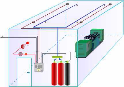
| If you do not wish or are unable to download the Flash player, below is a description of the Open Deluge System: | |||||||||||||
| Sequence of events for Open Deluge System |
Computer Aided Design
Water Mist FTL utilises independent third-party PC based software 'Piping Systems Fluid Flow' for simulation, design and analysis of Water Mist fire protection systems. Click below to view a typical system |
||||||||||||
| 1. If a fire is detected by a smoke sensor on either zone 1 or 2, the relevant red zone LEDs will pulse, the first stage alarms (Electronic Sounder and Xenon Beacon) will be activated and the first stage LED will be illuminated. Any Building Control Systems connected to the first stage relays will also be signalled. Typically this will include House Fire Alarm System, Air Conditioning Plant and Door Security Systems. | |||||||||||||
| 2. If a fire signal is then reported back to the Control Panel from another sensor on the second zone both zone LEDs will pulse, second stage alarms ( Bells ) will be activated and both first stage and second stage LEDs will be illuminated. Any Building Control Systems connected to the second stage relays will also be signalled. Typically this will include power supply to the risk area. The Timer Held LED will pulse to show that the extinguishant release timer is running. When the timer ends the Timer Held LED will be extinguished and the water mist system will be activated. | |||||||||||||
 |
|||||||||||||
| Pressing the manual release at any time will put the system straight into second stage and activate the timer for Water Mist discharge. | |||||||||||||
| 3. The solenoid valve on the Nitrogen system will be operated and Nitrogen at 200 bar will be released through the regulator which will reduce the pressure to 110 bar on entering the watermist valves. | |||||||||||||
| 4. A Flow switch on the manifold sends a signal to the Control Panel to indicate that the Water Mist has activated. The system will then discharge for the designed run time. | |||||||||||||